


Video Cables from the Inside Out
A review of the inner structure of video cables
So, what's in a video cable?
When reading descriptions of home theater cable products off of packages in a big-box store, or off of websites online, it's sometimes hard to get a clear understanding of just what, exactly, is inside a length of cable. It often isn't clear where the engineering-speak ends and where the marketing-speak begins, and the marketing-speak certainly isn't usually designed to aid understanding.
Beneath the fancy braided coverings, the colourful PVC, and the crimped, soldered and/or molded connectors, the inner structure of most video and audio cables is pretty simple and standard. That's not to say that all cables are constructed equally, but all well-made cables do share some basic structure in common.
Most video cable (leaving out of this discussion the parallel digital video standards, DVI and HDMI) is coaxial cable. Most people associate the term "coaxial cable," or its nickname, "coax," with RF video cables used for CATV distribution, or with coaxial digital audio cable used in handling SPDIF signals, but the fact is that "coax" is the basic design for every common analogue video standard, whether it's RF, composite, s-video, component, RGB, or SDI. While the cables used in these applications may differ from one another in a variety of ways, they're all coax, and are all designed and produced in more or less the same way.
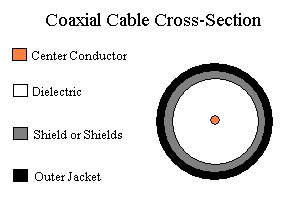 When you're trying to learn something about a particular manufacturer's video cable, there are really only four physical components to consider, and how those four components are built and interact accounts for everything a coaxial video cable does and for whether it does it well or poorly. These four physical components are all, in a straight run of cable, cylindrical in shape--because they share a common physical axis, which is what makes a cable "coaxial." These, in order from the inside to the outside, are the center conductor, the dielectric, the shield, and the jacket. If you cut through a piece of coaxial cable, you'll see them, laid out as in the drawing at right.
So, let's dissect this cable; we'll talk here about what job each of these four components does, and what kinds of materials and configurations they're commonly found in, and the advantages and disadvantages of different materials and constructions.
The Center Conductor:
At the center of the coax is a wire which we call the center conductor. In an obvious sense the center conductor does much of the business of the cable; after all, the function of a run of cable is to get an electrical signal from one end to the other, and that signal travels right down the center conductor. Doing the job well, however, as we'll see, involves the other elements of the cable to a surprising degree.
There are three principal ways in which the center conductor of one cable may differ from another; these are (1) wire gauge, (2) stranding, and (3) composition. How these affect cable performance is easy to understand.
Wire gauge is meaningful because it determines the resistance of the wire; the larger the wire, the lower the resistance, and therefore, all else being equal, the less signal loss ("attenuation") attributable to resistance there will be over any given length. But one can't just use a huge wire, slip a bit of insulation over it, put a shield over that, and have a good video cable; as a practical matter, wire gauge is limited by the need to keep video cables at 75 ohms impedance--about which more later.
Stranding is important because it affects flexibility and impedance tolerance. Stranded wire will be more flexible than solid wire of the same gauge, but because the surface of a stranded wire is more irregular, and because stranded wire can "open up" when flexed, it is harder to maintain a tight impedance tolerance--that is, to keep impedance very close to 75 ohms--with a stranded wire than with a solid wire. For this reason, performance and flexibility can present something of a tradeoff.
The composition of the wire is important because some metals conduct electricity better than others, and some have other characteristics which make for better wire than others. The universal choice in professional video cable for broadcast and post-production is copper, but one will also sometimes see coaxes which use copper-coated steel, silver, or silver-coated copper. Copper-coated steel is a sign that a cable was designed for CATV distribution; it's used because (1) it's cheaper than solid copper, (2) it's stronger (important if you're going to string cable in the air between buildings and poles), and (3) although steel is a poor conductor, the high frequencies used in CATV distribution primarily travel on the outer skin of the center conductor due to a phenomenon known as "skin effect1." Copper is the best overall choice for a video cable conductor because it is highly conductive--second only to silver, and that by a small margin--and because, unlike silver, it is extremely tolerant of bending. Silver, by contrast, is brittle and failure prone, so much so that most "silver" cables are actually made with copper wire with a microscopically thin silver plating, to allow the cable to flex normally without being damaged. Silver's only advantage is its very slightly higher conductivity as compared to copper--an effect which is often swamped by the insistence of silver-cable marketers upon using smaller-gauge cables whose conductivity (inverse of resistance) is significantly lower than that of a full-sized solid-copper cable design.
Beyond the obvious, there are some other attributes of a center conductor that can be important. We speak of "wire gauge" as though it's a constant, and as though the wire is a pure, perfect and smooth cylinder. In fact, all wire is, if examined closely enough, full of microscopic defects and irregularities. Wire can have periodicity from being drawn over out-of-round wheels or subjected to uneven tension; it can be less than perfectly round, because pressure was applied to it while it was being annealed; and while it is theoretically all the same gauge, in fact any run of wire, examined closely enough, will be seen to vary in size from point to point. These considerations usually aren't problems, but can be; and this is why it's always helpful to use cable from a supplier with a strong commitment to consistency and quality control. One of the many reasons we're particularly fond of Belden is that, unlike most of its competitors, Belden draws its own wire from raw copper rod stock, which allows it complete control over the quality of its wire and the ability to rapidly correct any deviation from spec.
The Dielectric:
In between the center conductor and the shield is the dielectric, a layer of insulation which prevents the signal from shorting out to ground. One might think that one sort of insulation would be just as good as another here--but in fact, the dielectric plays a critical role in cable performance because, by controlling the physical relationship between the center conductor and shield, it determines the impedance of the cable. Dielectric materials are compared against one another by reference to something called the "dielectric constant," which is basically a measure of how well the material isolates the center conductor electrically from the shield. The better a material is at isolating the conductors on each side, the lower its dielectric constant.
A low dielectric constant is good because the better the dielectric is, the closer together one can place the center conductor and shield. That means that for a given cable size, a better dielectric allows one to use a larger center conductor, which results in lower attenuation. This fact can, as we'll see, make the outer size of a cable somewhat deceptive; sometimes a cable that is large on the outside has a rather small center conductor inside, necessitated by the choice of dielectric material.
The best dielectric material (ignoring the perfect dielectric, a vacuum) is air. But of course, air has some rather obvious shortcomings as a cable construction material. The best dielectrics, in practice, are those which won't easily distort in shape, especially under the stress of cable flexing, which hold up to a wide range of temperatures, which can be easily formed in cable manufacture, and which have a reasonably good dielectric constant. The two leading materials for use as dielectrics in coaxial cables are Teflon and polyethylene, both of which satisfy these requirements quite well.
For years, the best video cables were built with solid polyethylene as the dielectric. Belden 8281, the old broadcast industry standard, is a solid PE cable. But solid PE has some downsides. In particular, it doesn't make for the best cable flexibility; 8281 is big, thick, heavy, inflexible cable, not very pleasant to work with, largely because of the solid PE dielectric. Also, while solid PE has a low dielectric constant as compared with other thermoplastics, it still can make for a rather large cable. One solution to this problem is to inject gas bubbles into the dielectric, using air (or, more often these days, nitrogen) to make the dielectric constant lower and make the dielectric more flexible. But until fairly recent times, it wasn't possible to make highly consistent foams with uniform bubble sizes and good resistance to crushing; impedance tolerance was loose, and the cables were vulnerable to damage. For the best broadcast-quality performance, solid dielectrics were more consistent and more robust.
Today, however, foam dielectrics are the rule rather than the exception. There are a lot of terms used to refer to foamed PE, and the fancier the marketing pitch, the fancier the name; when someone tells you that some cable is made with "microcellular gas-injected polymer" dielectric, or some-such, all that means is that it's PE foam. To know how good that is, you need to have a spec sheet from the manufacturer to tell you how tight the impedance tolerance is--by whatever name, there are good foamed dielectrics and not-as-good foamed dielectrics. Belden's HDPE (High-Density Polyethylene) foam is the industry leader, but there are other excellent products as well. The best foams use nitrogen because it lends itself to small, consistent bubble size (a phenomenon we can all observe at the tavern; draft Guinness Stout is nitrogen-injected, resulting in extremely small bubble size and a "creamy" consistency to the foam).
From time to time you'll see video cables made with Teflon, or foamed Teflon, dielectric. These cables are costlier, and have an important role in the professional world; but the high price has a way of leading people to suppose that the Teflon-dielectric cables are better, when they're not. The reason Teflon is used as a dielectric is to satisfy fire codes in situations (usually seen only in commercial buildings) which call for a "plenum-rated2" cable--to reduce toxic gases in the event of a fire--and not because Teflon makes a better cable. Because Teflon is harder to make into a consistent foam than PE, Teflon dielectric cables generally underperform their polyethylene counterparts somewhat; for example, Belden 1694A, a foam PE cable, has an impedance of 75 ohms +/- 1.5 ohms, while Belden 1695A, the plenum version, has an impedance of 75 ohms +/- 3 ohms. There's nothing wrong with 1695A; but since it costs over three times as much as 1694A, which outperforms it, there's no reason to buy the plenum cable unless you have a plenum installation.
Foam PE dielectrics have allowed video cables to shrink dramatically in size. Remember Belden 8281, mentioned above? 8281 has an outer diameter of .305 inch, significantly larger than 1694A, Belden's best RG-6 sized video cable at .275 inch; yet, 8281 is an RG-59 type--with a smaller center conductor than 1694A. Today's cable is smaller on the outside, bigger on the inside, more flexible, lighter, and tighter in specs--and whether one calls it "foamed plastic" or "space-age microcellular nitrogen-injected precision polymer," the credit goes to the modern PE foam dielectric.
The Shield or Shields:
Outside of the dielectric lies the shield. The shield has two obvious functions: it joins the ground side of the circuit at both ends of the cable, and it provides shielding, absorbing electrical noise from the outside world and shunting that noise to ground to keep it out of the signal path. The first of those tasks is pretty simple; shield effectiveness in keeping noise out of the signal path, on the other hand, is less straightforward.
Most coaxial shields are either made of foil of of braided wire, and most coaxes use some combination of these two shield types. That's because foil and braid each have distinct advantages in providing shielding. Foil has the obvious advantage of high coverage; it's pretty easy to see how a layer of foil can be applied to the outside of the dielectric in such a way as to completely enclose it, so that any outside noise that is headed for the center conductor will be forced to encounter the shield first. But foil is fragile, it's not very conductive, and it's hard to make a good, solid connection--especially one that will endure flexing in use--between foil and any common type of connector.
Braid, by contrast, is easy to apply connectors to; it can be highly conductive, because it can be made with as much metal as is considered desirable, and it will endure many, many flexes without breaking or failing. But braid, unlike foil, can never offer full coverage. Any braid has tiny holes in it, and no braid offers more than about 95% coverage. When braid is flexed, it opens those holes up wider still.
Braid and foil complement each other in frequency coverage, too; a braid-only shield is quite effective at low frequencies, and its effectiveness diminishes at higher frequencies. A foil shield is rather ineffective at low frequencies, and becomes more effective at higher frequencies.
Since the two shield types complement each other, they are often seen together. This combination of shields results in cables being referred to as single-shield, dual-shield, triple-shield, or quad-shielded cables--but this way of referring to cable sometimes leads to erroneous assumptions about what type of cable is best shielded. In particular, it is often assumed that quad-shield cable is the best-shielded, because, after all, it has more shields than any of the others. That's not so, because it isn't just the number of shields that matters; it's their quality.
Foil can be single-layered or multiple-layered, and can be folded together so as to close the shield; how the foil is applied to a cable, therefore, can affect its effectiveness as a shield. But the big difference between shields usually comes in the braids. A cheap CATV distribution coax will typically have foil with a 60% coverage aluminum braid. Big holes are left, there's not a lot of wire in the shield, and aluminum isn't as conductive as copper, so the ability of the shield to shunt noise to ground is compromised. The best coaxes made specifically for CATV distribution are quad-shielded, which adds another layer of foil and another, even thinner, 40% aluminum braid. That gives a net braid coverage of 76%; still a lot of holes, and not the best conductivity to ground.
The best shielding for video covers the whole RF range with a combination braid and foil. But the braid in a truly well-shielded cable is copper, not aluminum, and its coverage is 90% or more. This use of a substantial amount of copper in the shield, with high coverage, gives very low resistance to ground and the best RFI rejection available.
The Jacket:
There's not much to say about the outer jacket of a video cable; it ought to be physically durable, and provide good insulation, but because it doesn't act as a dielectric, its electrical properties are otherwise unimportant. The most common material in use is PVC, which has the advantages of reasonably good flexibility and cut resistance, and can be dyed to just about any colour desired. Contrary to what many believe, the jacket adds nothing to shield effectiveness; its only functions are insulation and protection of the cable from physical damage.
Cable Gestalt: What the Parts do Together.
How the components of a video cable work together is important, because a video cable should be made to have a 75 ohm "characteristic impedance," to match the impedance of video equipment inputs and outputs. Characteristic impedance is a strange sort of electrical characteristic--people often wonder why a video cable won't measure 75 ohms on a volt-ohmmeter, and consequently wonder whether this "75 ohm" thing means anything at all. It certainly does, though it's not the easiest cable property to understand.
Basically, all that having a 75 ohm characteristic impedance means is that when a cable is hooked up to a 75 ohm signal source and a 75 ohm destination, both of which are intended to be hooked to other 75 ohm impedance devices, the cable doesn't alter the way that the source device's impedance "looks" to the load, or vice versa. If a cable isn't of the right impedance, especially when the cable is of length approaching or exceeding the signal wavelength, the cable itself becomes a factor in the circuit, and an impedance mismatch results; this causes parts of the video signal to reflect within or off of the ends of the cable when they should simply be delivered to the device at the load end, and in a severe case, this can result in "ringing" or ghosting of the image.
So, how is the impedance of a cable established? In a perfect world, where dimensions of things can be treated as constant and well-defined mathematical values, it depends on only three things: the outer diameter of the center conductor, the inner diameter of the shield, and the dielectric constant of the material between them. In the real world, of course, materials aren't perfect; no wire is of perfectly consistent dimensions, no cable has a perfectly consistent shape, no dielectric foam has a perfectly consistent bubble size and distribution, no center conductor is perfectly centered, and cables don't just go in straight lines; they flex, and when they flex, these dimensions and relationships are altered. All of these real-world factors have to do with the actual, in-use characteristic impedance of a cable.
Because no cable is perfect, characteristic impedance isn't perfectly constant even in the best-built cables, and so video cables are engineered to meet an "impedance tolerance," that is, to be within a given tolerance of 75 ohms. To achieve a tight tolerance, a manufacturer has to meet very high standards of consistency. Wire must be drawn to precise, reliable size; it can't vary meaningfully from foot to foot. Dielectric foam must be of highly consistent texture, and must be extruded over the wire with close control over centering. Shields must follow the contour of the dielectric closely. The behavior of all of these elements must allow the cable to be flexed as normal in use without causing the center conductor to cut its way through the dielectric and wind up off-center. If all of these and other elements are well-controlled, the result is a cable with a tight impedance tolerance; the best precision video cables today are rated at +/- 1.5 ohms, and even the high-flex cables come within +/- 3 ohms. The tighter that tolerance, the less likely problems with impedance mismatch are.
Conclusion:
Cable isn't magic, and the characteristics of a video cable that make it what it is and make it do what it does are well understood. If you're shopping for cable and can't make heads or tails of a seller's claims, ask for a spec sheet; find out what the attenuation chart says at the frequencies in question; see what the impedance tolerance of the cable is; ask whether it's been sweep-tested. Any manufacturer of cable for the professional market--where standards are far more demanding than in any home theater application--can produce a full spec sheet on any of its products. In the home theater market, the consumer has the right to expect no less, and the products which meet the highest professional standards will always come with specs to vouch for them. No engineer in a production facility buys a cable because the manufacturer promises "blacker blacks" or "crisper definition"; he knows that the cable which delivers the cleanest and most faithful signal will be the one that has met or exceeded the most demanding engineering standards of impedance tolerance, shield effectiveness and the like. A good spec sheet allows one to look at a cable's performance from the inside out, instead of having to squint, guess and hope.
Footnotes:
1. "Skin effect" is a very real and well-understood phenomenon in electrical theory; the higher the frequency of a signal, the more it tends to travel on the outside, rather than the inside, of a conductor. Because so many flaky, snake-oily and just plain wrong claims are made about skin effect in connection with the sale of cables, we've found that many people assume that the phenomenon of skin effect is just another myth. It's not, but that doesn't mean you should believe everything you hear about it.
2. In general, a plenum rating is required when cables are being installed in a space used as an HVAC return duct space. The most common example is a typical ceiling cavity in a commercial building. A dropped ceiling which isn't being used as an air return (e.g., most dropped ceilings in residential installations) does not require a plenum cable.